By Jett Peters
Polar alignment is perhaps the biggest challenge for the beginner entering astrophotography with an equatorial mount; it remains an important step all the way up to the expert level. Whether polar aligning in your backyard for a single night or at a remote observatory where the telescope will reside for years, it is a crucial mechanical step.
Before we discuss a few tools and methods for achieving accurate polar alignment, we should define why it is so important. The vast majority of astrophotography mounts are of the German equatorial design. This means they use two orthogonal axes to move the telescope to a place in the night sky and to counteract the rotation of Earth. The mount is aligned so the right ascension axis points directly at the north celestial pole. In this orientation, counteracting rotation can be relegated just to the right ascension axis; the declination axis merely serves to point the telescope to a given position in the night sky.
Manual Alignment
The first polar alignment method is the least accurate, as it depends entirely on the observer’s eyesight and accounts for only a single position in the sky. Many mounts include a built-in polar scope, though one can also be fixed externally. This instrument is essentially a small telescope fitted with a reticle, and the procedure consists of positioning Polaris at a prescribed point on the reticle’s outer disc. Because Polaris does not coincide with the true celestial pole, it traces a small circle around the pole over the course of the night. Consulting a polar clock is therefore necessary to determine where along this rotation Polaris should be placed at the moment of alignment.
Advantages
- Speed: The process is fast and minimal equipment is required.
- Experience: Many astronomers enjoy disconnecting from technology and working hands-on with their equipment.
Disadvantages
- Error: What is gained in speed is lost in precision. Because the method relies on human eyesight, accuracy suffers significantly.
- Incompatibility: Many modern mounts do not incorporate a polar scope, and some offer no way to attach one externally.
Who It’s For
This method is primarily suited to beginners or visual astronomers who either lack or prefer not to use the technology required by other alignment methods. For beginners in particular, it offers the dual benefit of becoming familiar with one’s equipment and developing an understanding of mount mechanics.
Multi-Point Plate-Solve Alignment
The second method comprises multi-point plate-solving routines, of which the most widely used are the Three Point Polar Alignment plug-in for N.I.N.A. and SharpCap’s polar alignment tool. Both rely on plate-solving combined with controlled mount rotation to yield a far more accurate estimate of polar alignment than visual methods can achieve. The principle is straightforward: an image is captured at a known mount position and plate-solved to obtain its precise (RA, Dec) coordinates. The mount is then rotated about its RA axis to a new position, and the process is repeated. By comparing the resulting positions, the routine can infer where the RA axis is actually pointing.
While the specific mathematical implementations vary between tools, the underlying principle is simple. When a mount is rotated about its Right Ascension axis, the telescope traces a circle across the sky. By measuring multiple points along this arc, the software can determine the center of that circle. This point represents the mount’s current mechanical axis; polar alignment is then perfected by adjusting the mount until this axis is aimed exactly at the celestial pole.
Tools Using the Method
- SharpCap Polar Alignment
- N.I.N.A. 3-Point Polar Alignment
- ASIAIR Polar Alignment
Advantages
- Speed to Accuracy: Since most of the routines in this category explicitly break down the error by azimuth and elevation, no guesswork is involved. The accuracy of this method is very high.
- Ease of Use: If an astrophotography setup is assembled and on the tripod, the routine can be run with very little effort. Every step up to the adjustment is automated and requires no mechanical alteration of the setup.
- Accessibility: Most of the software solutions that utilize this method are likely already installed on your imaging computer, and contain step-by-step instructions.
Disadvantages
- Conflated Errors: While generally speaking, these methods are accurate, additional error can creep into the measurement that is not actually caused by polar error. Factors like atmospheric refraction, mechanical flexure, and cable drag can trick the software into seeing a polar error that is actually just a physical shift in the equipment.
Who It’s For
This method is suitable for the majority of astrophotographers. It is quick to use, simple in its instructions, and achieves a high degree of accuracy. Whether setting up for a single night’s acquisition or deploying at an observatory, it is a strong candidate. However, if results differ between runs, the next option is encouraged.
Guide-Based Drift Alignment
The gold standard among polar alignment routines is the guide-based drift alignment found in PHD2. This method directly measures the very behavior we wish to eliminate: declination drift. As established, a star moves significantly in Right Ascension due to Earth’s rotation, but it should remain perfectly stationary in Declination if the mount is correctly aligned. By disabling guiding on the Dec axis and measuring the drift rate of a star’s centroid, we can determine the magnitude of polar error with a high degree of precision. The challenge lies in separating this error into its two components: Azimuth and Altitude. The solution is found in the drift equation:
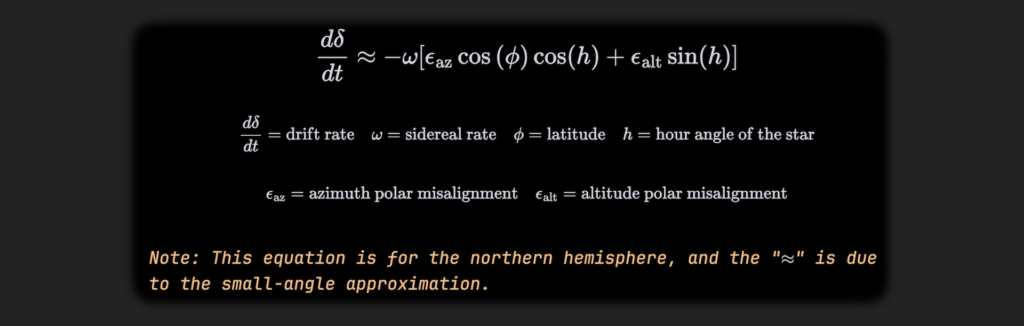
Since sine of zero is zero, using an hour angle of zero makes the drift only a consequence of azimuth error. Choosing an hour angle of plus or minus 6 hours, near the eastern or western horizon (corresponding to 90 degrees), eliminates the azimuth term in the equation, leaving us only with a drift caused by elevation. PHD2 uses these two sky positions in order to estimate polar error.
Advantages
- Accuracy: Drift alignment yields the highest accuracy among polar methods.
- Outcome: The method actually addresses the problem of poor alignment at its source. Rather than requiring a system of plate-solved images, it directly uses the movement of a star in Dec as the measure.
- Accessibility: PHD2 is already used by most astrophotographers, and the tool is built directly into the software.
Disadvantages
- Time: Drift alignment takes a long time. In order to obtain an accurate estimation of the error, the drift rate needs to stabilize, which takes time. The closer to perfect the alignment, the longer it takes to measure a drift.
- Conflated Errors: Drift alignment is the gold standard only when the mechanical system is rigid enough that drift truly reflects the polar axis and not the imaging train settling under gravity. Differential flexure between the guide scope and the main OTA is the most common culprit to keep in mind.
Who It’s For
This method is suitable for permanent and semi-permanent installations, where accuracy is the overwhelming priority. The difference in accuracy between tools like SharpCap and drift alignment may be subtle, but it is necessary for certain types of systems. Those wishing to do unguided imaging at long focal lengths should consider using this method.